Sim, deveria aparecer esse menu e os io configurados aparecem como relés no tasmota, como se fossem relés de gpios nativos…
Depreendo que também tenhas activado o próprio pcf e não só a morada dele…
Referes-te activar PCF na compilação? é #define USE_PCF8574 certo?
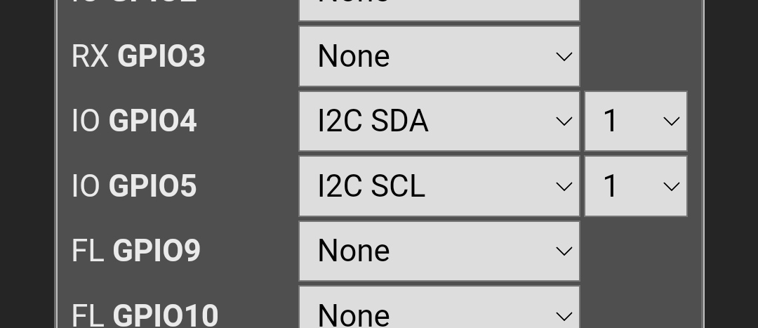
No PCF8574 não foi preciso definir ADDRESS , parece que para os MCP23xxx é necessário :
#define USE_MCP230xx                 // [I2cDriver22] Enable MCP23008/MCP23017 - Must define I2C Address in #define USE_MCP230xx_ADDR below - range 0x20 - 0x27 (+4k7 code)
#define USE_MCP230xx_ADDR 0x20       // Enable MCP23008/MCP23017 I2C Address to use (Must be within range 0x20 through 0x26 - set according to your wired setup)
#define USE_MCP230xx_OUTPUT          // Enable MCP23008/MCP23017 OUTPUT support through sensor29 commands (+1k5 code)
#define USE_MCP230xx_DISPLAYOUTPUT   // Enable MCP23008/MCP23017 to display state of OUTPUT pins on Web UI (+0k2 code)
.
Entretanto lá dei mais uns passos …
Na compilação no passo 4 tem de se introduzir
#define USE_PCF8574 // [I2cDriver2] Enable PCF8574 I/O Expander (I2C addresses 0x20 - 0x26 and 0x39 - 0x3F) (+1k9 code)
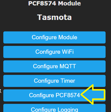
Depois de flashado o firm, na consola activa-se o driver
i2cdriver2 1
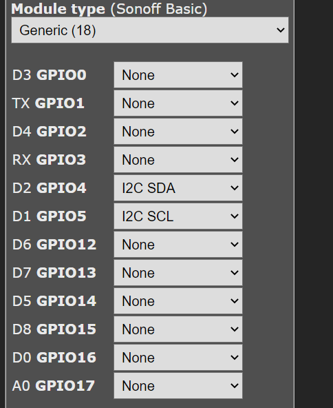
E lá aparece o menu
.
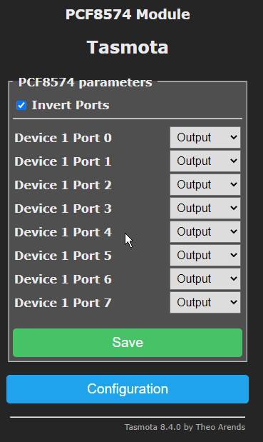
Depois podemos configurar os 8 IO como input ou output
.
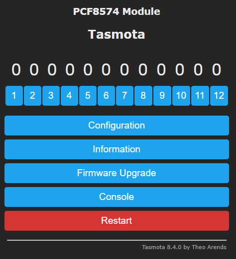
E já aparecem mais 8 reles para alem dos 4 que configurei no NodeMCU
.
Agora quase lhe posso chamar sonoff 12CH, se acrescentar mais uns PCF8575 ( ainda não chegaram os MCP para testar ) que posso tirar dos LCD que tenho no monte , facilmente se deve conseguir expandir para mais uns quantos IO e passa sonoff 32CH, o equivalente a uma carta de automato por menos de 10€ 
Sabes qual o limite de nós/enderesos no i2c?
EDIT: Actualizado no 1º post
Em princípio serão possíveis 32 relés, mas, pelo menos até há pouco tempo, seria necessário fazer uma alteração no código do tasmota para isso… Neste momento não tenho a certeza… O pcf apenas pode ser usado como output no tasmota porque o driver nunca foi acabado…
Já o MCP pode ser usado como input e output, mas, até há pouco tempo, os outputs não apareciam como relés nem os input como switch, ou seja, para os activares directamente precisavas de rules, mas era possível. Entretanto, foi feita uma mudança ao driver e já devem aparecer como relés,mas não testei…
@Maddoctor
Confirma-se que o PCF no TASMOTA apesar de se poder configurar os IO para output ou input , só funciona como output, pelos menos o state dos input´s não aparecem publicados na consola. Se calhar tb precisa de algumas rules como dizes necessárias para o MCP.
Se usarmos ESPHome já dá para usar o PCF como input ou output, a interface do ESPHome é que … não ajuda
não, os input não funcionam mesmo no pcf em tasmota… com ou sem rules…
Resumindo, para expander de IO em tasmota é melhor os MCP23017
Não é bem… Depende dos usos… O pcf está mais “integrado”, com a página de configuração e tal…mas o MCP tem mais IOs e permite inputs…
@PDM Sorry for writing in English, but I hope you’ll understand my question: Very nice post! I’m using an ESP-01 board with SCL=0 and SDA=2 (I need RxD and TxD as well so this is the only chance…) and I followed all the steps you mentioned. “i2cscan” returns the correct connections (one PCF8574 in my case), but when I enter i2cdriver2 1, the command is obviously accepted, but the ESP resets without enabling the “Configure PCF8574” menu. Any idea? Can you please share your .bin file for me to test?
Answering in Portuguese is welcome for sure as well. 
I already left the idea of the PCF because I think that with MCP and Esphome it will be a better option because it allows you to add more than one device as opposed to the tasmota that only allows one.
However to confirm that it works with tasmota 9.2.0, I did the test with wemos D1 with firmware 9.2.0 compiled with tasmocompiler and it is working.
Firmware compiled with:
#define USE_I2C
#define USE_PCF8574
1 Curtiu
The module is working now (ESP-01 with SCL = GPIO0, SDA = GPIO2) after I changed the I²C address of the PCF8574 from 0x27 to 0x23 => Tasmota bug or intended function? I don’t know…

My module add is 0x23, probably for that reason it worked.
I found this in the tasmota documentation
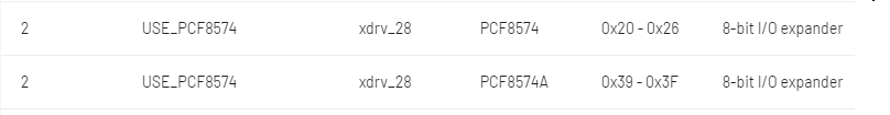
you’re right. I would have been happy if I saw it at the beginning 
Yes, 0x27 seems to be reserved for a display, but anyway, I’m happy, it’s working even if I have to solder some small wires to all my PCBs.
1 Curtiu
Now I can configure each pin of the PCF8574 as input or output, but where can I see the input information? 
In 2020 August , when I tested the PFC, the inputs were not supported by the driver, I believe that today they are also not supported.
As I said earlier, I ended up opting for MCP23xxx and EspHome, where I managed to do tests with input and outputs, I still didn’t have time to go beyond the tests, the idea was to implement a device with at least 16 relay with 16 inputs for buttons using at least 2 MCP23017
Estou a fazer um projeto idêntico com um MCP23017 só que não consigo adicionar o menu para atribuir os ios através da pagina web, sabem se é possível?
Tens de compilar a firmware
Estou a experimentar com os passos acima referidos.
Compilei o firmware com as opções:
#define USE_MCP230xx
#define USE_MCP230xx_ADDR
#define USE_MCP230xx_ADDR 0x20
#define USE_MCP230xx_OUTPUT
#define USE_MCP230xx_DISPLAYOUTPUT
Depois na consola:
i2cdriver2 1
Com o i2cscan ele encontra o MCP23017 só que na página web não adiciona nenhuma opção para configurar os IOS
Tens de configurar o I2C primeiro